


Problem & Solution
Standard parallel 16x2 character LCD screens consume at least 6 digital I/O pins on microcontrollers like the Arduino Uno. This heavy pin footprint leaves very few microcontroller pins available for connecting sensors, motor drivers, relays, and other peripheral hardware. Furthermore, wiring a 16-pin bare LCD module often leads to cluttered breadboards and tedious circuit troubleshooting.
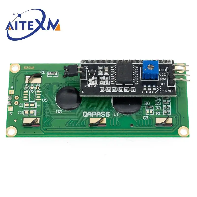
The LCD1602 I2C Display Module addresses this challenge by attaching a PCF8574 I2C serial backpack board directly to the rear of the character LCD. By converting parallel data lines into the two-wire I2C protocol, it streamlines the required connections down to just two signal lines (SDA and SCL) plus two power connections (VCC and GND).
Who Is It For?
This display module is tailored for electronics hobbyists, engineering students, robotics builders, and hardware developers prototyping projects on Arduino, ESP8266, ESP32, or Raspberry Pi boards.
It is ideal for projects that require straightforward text readout—such as sensor telemetry monitoring, real-time counters, status notifications, or menu navigation—without wasting valuable microcontroller input/output pins.
Key Features
- Integrated PCF8574 I2C Serial BackpackConverts 16-pin parallel LCD control down to a simple 4-pin interface (VCC, GND, SDA, SCL)
- 16x2 Character Display CapacityDisplays up to 32 alphanumeric characters across two distinct rows
- 5V DC Power CompatibilityConnects natively to 5V power supply outputs on popular microcontroller development boards
- Built-in Potentiometer TrimmerEnables quick manual adjustment of display screen contrast using a small screwdriver
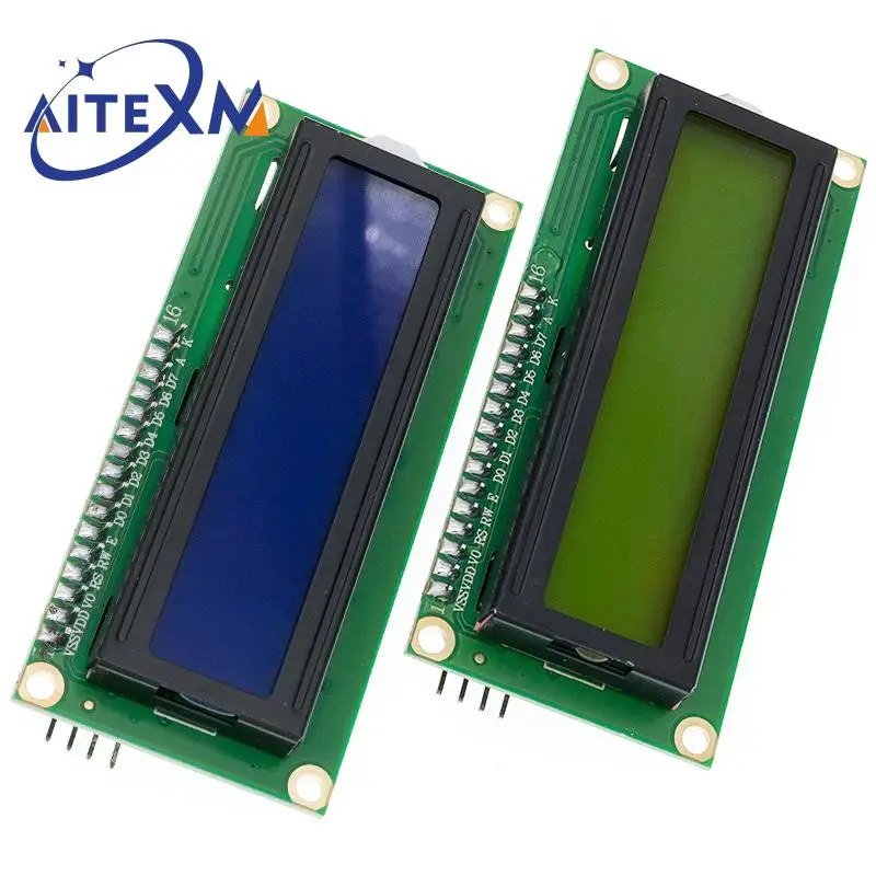
- Blue and Green Screen OptionsAvailable with a high-contrast blue backlight with white characters or a yellow-green backlight with dark characters
Technical Specifications
| Display Capacity | 16 Characters x 2 Lines (1602) |
| Interface Backpack | PCF8574 I2C / IIC Serial Adapter |
| Operating Voltage | 5V DC |
| Required Interface Connections | 4 Pins (VCC, GND, SDA, SCL) |
| Screen Color Variants | Blue Backlight / Yellow-Green Backlight |
| Contrast Adjustment | Integrated Potentiometer Trimmer |
| Communication Bus | I2C / IIC Protocol |
| Physical Dimensions | not specified in available data |
| Weight | not specified in available data |
Pros & Cons
Pros
- Significantly reduces microcontroller pin usage via 2-wire I2C communication
- Onboard potentiometer simplifies screen contrast tuning
- Broad software support with widely available open-source libraries (e.g., LiquidCrystal_I2C)
- Substantially reduces breadboard jumper wire clutter
Cons
- Designed for 5V operation, which may require logic level shifting when pairing with 3.3V microcontrollers
- Limited strictly to alphanumeric text and basic custom characters (no graphical bitmaps or color graphics)
- I2C hex address can vary between PCF8574 chip revisions, requiring an address scanner code sketch during initial setup
FAQ
The module requires 4 pins total: two pins for power (5V VCC and GND) and two digital pins for I2C data transfer (SDA and SCL).
The module operates on a standard 5V DC power supply.
Turn the small blue potentiometer dial located on the rear PCF8574 adapter board to adjust the display contrast level until the characters become visible.
Most PCF8574 adapters use either 0x27 or 0x3F as their default I2C address. Uploading a simple I2C scanner sketch to your microcontroller will reveal the precise address.
Final Verdict
A reliable display solution for makers building microcontroller hardware prototypes where saving GPIO pins is paramount. Highly recommended if you need text-based telemetry displays for Arduino or embedded system projects. Skip this module if your application requires high-resolution graphics, color images, or rapid animation. Always confirm microcontroller voltage compatibility prior to wiring.