

Problem & Solution
When debugging digital circuits or probing integrated circuits (ICs) with logic analyzers, connecting standard rigid jumper wires directly to small IC pins or surface-mount components often leads to unstable contact or accidental short circuits. Standard header pins lack grabber mechanisms, making hands-free signal testing difficult on populated printed circuit boards.
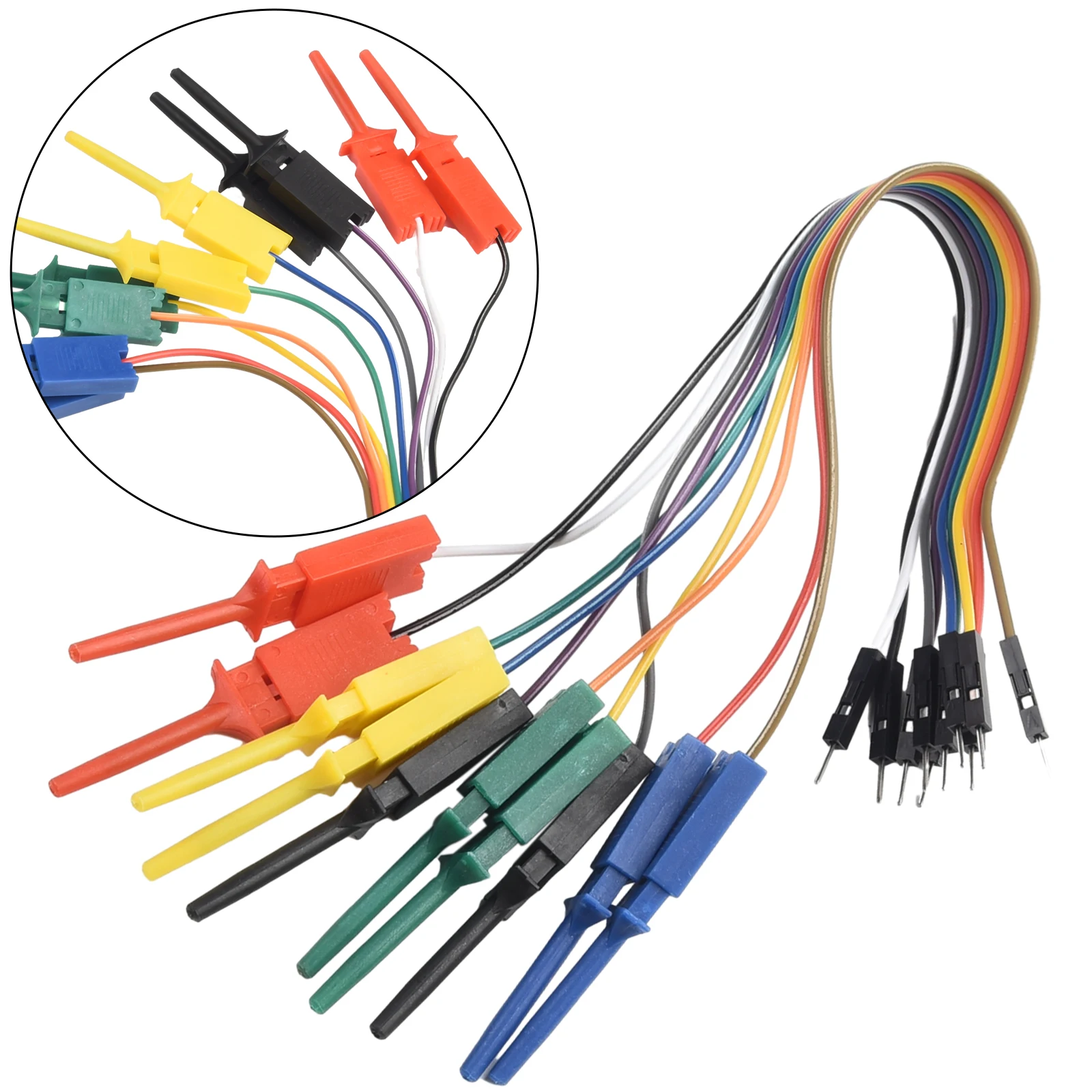
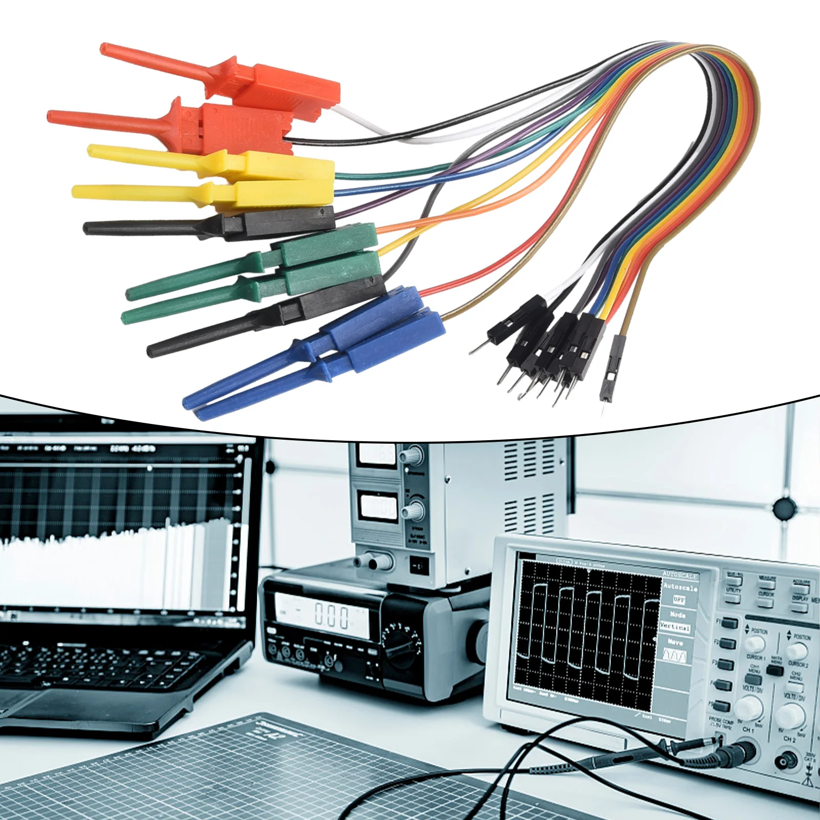
This 20cm 10-pin test lead assembly solves this diagnostic issue by pairing flexible wiring with mini test hook clamps. The spring-loaded grabber hooks securely clip onto fine component legs and IC pins, maintaining steady signal connection without needing manual holding, which keeps test setups clean and organized during logic capture.
Who Is It For?
Designed specifically for electronics engineers, embedded systems developers, hardware technicians, and microelectronics hobbyists. It is ideal for users connecting logic analyzers or signal diagnostics equipment to microcontrollers, custom circuit boards, SPI/I2C communication buses, and IC pins.
Key Features
- 10-Pin Signal InterfaceEnables simultaneous tapping of up to 10 digital lines or logic channels for comprehensive signal monitoring
- 20cm Lead LengthProvides standard reach across circuit boards without causing excessive cable clutter on the workbench
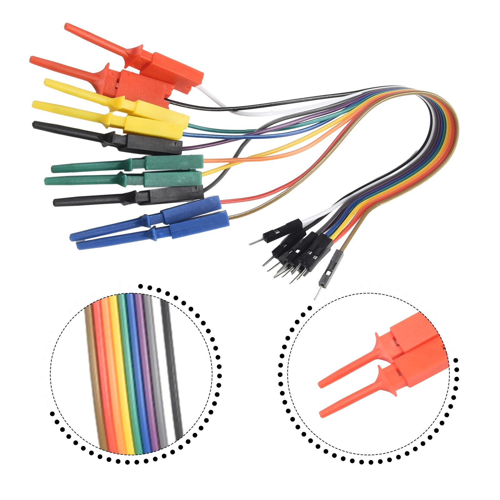
- 5 Color-Coded Wiring SchemeHelps distinguish channels visually, reducing indexing errors during multi-trace signal collection
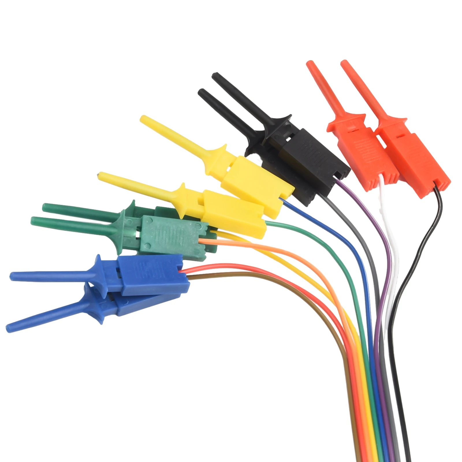
- Spring-Loaded Mini Hook ClampsAttach firmly onto small chip legs, headers, and component leads for reliable hands-free probing
- Integrated Multi-Lead AssemblyStreamlines cable routing between standard logic analyzer test interfaces and target boards
Technical Specifications
| Product Category | Logic Analyzer Test Lead Cable Assembly |
| Total Channels / Pins | 10 Pin |
| Cable Length | 20 cm |
| Probe Terminal Type | Spring-Loaded Mini Hook Clamps |
| Color Scheme | 5 Colors |
| Primary Application | Digital circuit debugging, IC pin probing, logic analyzer connection |
| Voltage / Current Rating | Not specified in available data |
Pros & Cons
Pros
- Includes 10 individual signal lines for multi-channel digital logic testing
- 20cm cable length offers adequate clearance on standard test benches
- 5-color wire coding aids quick channel identification
- Spring hook grabbers allow firm connection to fine electrical test points
Cons
- Maximum current and voltage tolerances are not specified in the available data
- Wire gauge and shielding parameters are not detailed for ultra-high-speed signal isolation
FAQ
The harness measures 20 cm in length, which is a standard practical size for electronics bench testing.
It supports up to 10 distinct connection channels via its 10-pin configuration.
The probe ends feature mini spring-loaded test lead hook clamps designed to grab hold of IC leads and small wire leads.
Yes, the 10 leads incorporate a 5-color scheme to assist in organizing and tracking individual signal channels.
Final Verdict
A practical logic diagnostic accessory recommended for hardware developers and technicians requiring a 10-channel grabber lead set for microelectronic debugging. Skip this set if you require shielded high-voltage probes or specialized high-frequency coaxial test leads. Verify your logic analyzer's header interface pitch before ordering.